L’impression 3D peut sembler être un champ de mines, mais ce n’est pas forcément le cas.

Chaque imprimante 3D et chaque technologie possèdent des capacités d’impression différentes, et des fonctionnalités communes sont utilisées dans l’industrie pour les tester. L’équipe de Ricoh 3D utilise plusieurs scénarios bien documentés pour recommander des points clés à prendre en compte lors de la phase de conception.

Suivez notre guide de conception d’impression 3D simple pour vous aider à sélectionner les meilleurs matériaux et techniques pour votre projet.

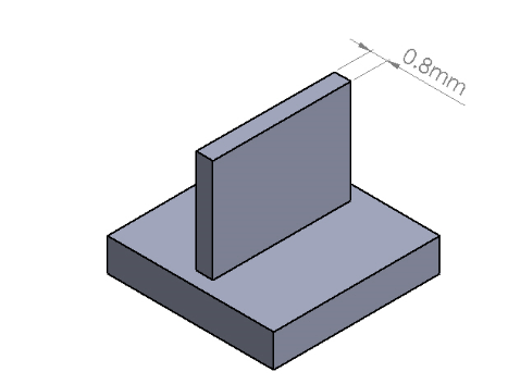
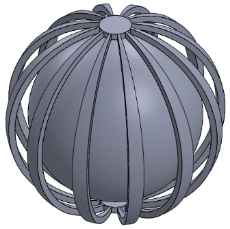
Taille minimale des fonctionnalités

Il s’agit de la taille minimale que nous pouvons garantir pour l’impression. Toute fonctionnalité inférieure à cette taille pourrait ne pas être reproduite par l’imprimante.

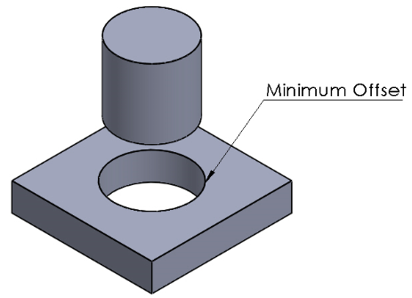
Décalages et pièces mobiles

Il s’agit de la distance minimale requise entre des pièces multi-corps pour obtenir un ajustement libre, permettant ainsi la libre circulation des pièces. Toute fonction inférieure à cette valeur peut être produite comme une seule pièce ou fonction et ne pas fonctionner comme prévu.
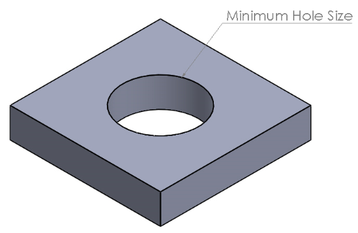
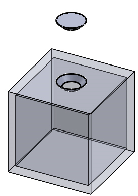
Trous

Il s’agit de la taille minimale requise pour que l’imprimante puisse reproduire un trou propre.
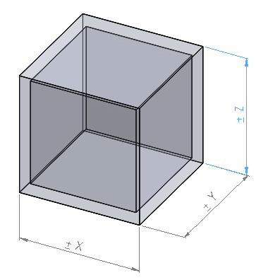
Tolérances

Il s’agit de la tolérance acceptée pour chaque technologie qui doit être prise en compte lors de la phase de conception.

Printing Type SLS HSS / MJF FDM
Minimum Feature Size
Minium Feature Size Illustration

Minimum Feature Size

The minimum size that we can guarantee the printer will be able to print. Any features under this size may not be reproduced by the printer.

0.8mm-1.0mm 0.5mm 1.0mm
Minimum Offset
Minium Offset Illustration

Minimum Offset

The minimum distance required between multi body parts to achieve a clearance fit allowing the free movement of parts. Any features under this value may end up being produced as one part or feature, and may not function as intended.

0.3mm 0.3mm 0.5mm
Minimum Hole
Minium Hole Size Illustration

Minimum Hole Size

The minimum size required for the printer to reproduce a clean hole.

1.5mm 1.5mm 2.0mm
Tolerance
Tolerance Illustration

Tolerance

The expected deviation in size that is likely to occur during the printing process.

±0.3% per 100mm (lower limit 0.3mm) ±0.3% per 100mm (lower limit 0.3mm) ±0.3% per 100mm (lower limit 0.3mm)
Support Considerations

If the part is to be free from unsintered powder then any hollow sections without an opening (in the design) will need to have a drain hole added and bonded into place after the manufacturing process. Without the drain hole the unsintered powder is impossible to remove and will remain contained within the part.

It is recommended that any sections greater than 6mm in thickness are hollowed in order to maintain part geometry. This will be done by the RICOH Rapid Fab team prior to printing and does not need to be considered during the design stage.

Drain holes and hollowing of thick sections will be added by our engineers prior to printing. We will always seek approval from the customer prior before printing.

All files sent to us are analysed prior to the printing process. We will advise of any issues with the geometry that may lead to problems during the printing or post processing stage.

If the part is to be free from unsintered powder then any hollow sections without an opening (in the design) will need to have a drain hole added and bonded into place after the manufacturing process. Without the drain hole the unsintered powder is impossible to remove and will remain contained within the part.

Drain holes and hollowing of thick sections will be added by our engineers prior to printing. We will always seek approval from the customer prior before printing.

All files sent to us are analysed prior to the printing process. We will advise of any issues with the geometry that may lead to problems during the printing or post processing stage.

The majority of FDM materials have soluble support material. So as long as water can enter the supported areas, this material is simply washed away.

Materials such a ULTEM and PC do not have a soluble support material option so 'break away' support material is used, meaning it has to be removed by hand with tools. If the support material is not accessible or simple to remove then it may be difficult to achieve the desired design, which limits the complexity of design for these materials. A ball-within-a-ball structure for instance (pictured) would not be possible with ULTEM or PC.

All files sent to us are analysed prior to the printing process. We will advise of any issues with the geometry that may lead to problems during the printing or post processing stage.

Besoin d’aide ?

Que vous recherchiez un conseil à propos de matériels, d’un devis ou si vous voulez tout simplement en savoir plus sur la fabrication additive, nous serons ravis de vous aider.
  • Nous appeler

    +44 (0) 800 304 7196

  • Nous contacter

    Nous contacter

    nous envoyer une demande